

How To Add Gpio To A Pc
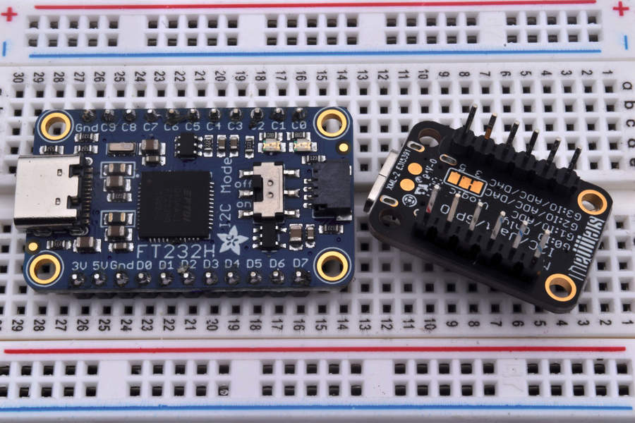
Thanks to the Raspberry Pi and Arduino, we are familiar with the GPIO (full general purpose input/output) that enable these boards to interface with real-earth electronic devices. PCs are devoid of a GPIO but boards such as Adafruit'southward FT232H are available that provide that functionality via a USB port.
CircuitPython Installation
We'll be using Python to work with these boards. Although this may already exist installed on your system, there are supporting elements you'll need to install. These come in the grade of CircuitPython, a version of MicroPython for microcontrollers such as the Raspberry Pi Pico. To setup the FT232H follow Adafruit'due south installation instructions for your operating system.
Earlier you do anything more with your FT232H, yous'll need to solder on the headers provided. We have a great guide on how to solder header pins to your lath.
To write the lawmaking for this projection you will demand an editor. For example you lot can utilise Notepad++, Visual Studio Code, PyCharm or any you are comfortable with.
Controlling the GPIO
In that location's a seemingly endless listing of projects y'all tin can create when you lot add together GPIO pins to a PC, only below we'll bear witness you lot how to code and wire a really simple i where a button causes an LED to illuminate.
i. Create a file and save information technology equally FT232H-example.py
two. Import ii modules of pre-written code. The first "lath" enables the code to talk to the FT232H, the second "digitalio" is how nosotros control the configuration of GPIO pins.
import board import digitalio iii. Create an object "led" which volition exist used to reference the LED connected to GPIO C0.
led = digitalio.DigitalInOut(board.C0) 4. Set up the LED object as an output, then that current flows to the LED from the GPIO pivot
led.management = digitalio.Management.OUTPUT 5. Create some other object, "push button." This is used to reference the push button button continued to GPIO pin C1.
button = digitalio.DigitalInOut(board.C1) 6.Gear up the push every bit an input.
button.direction = digitalio.Direction.INPUT 7. Within of a loop, set the value of the LED to friction match that of the button. When the button is pressed, the LED will calorie-free, when released, the LED will turn off.
while True: led.value = button.value Consummate Code Listing
import lath import digitalio led = digitalio.DigitalInOut(board.C0) led.direction = digitalio.Direction.OUTPUT button = digitalio.DigitalInOut(board.C1) button.direction = digitalio.Management.INPUT while True: led.value = push.value Creating the Circuit
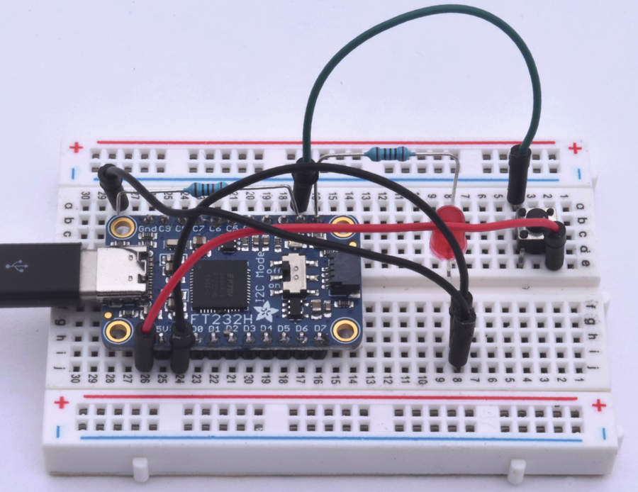
The excursion for this project is elementary. We have an LED connected to C0, and to GND via a 100 Ohm resistor. The button button is connected to 3.3V and C1. The resting state of C1 is OFF, and this state is the value used to turn off the LED.
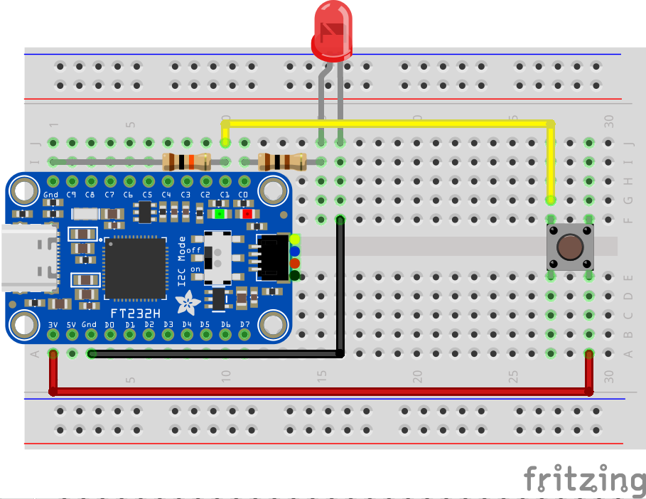
To ensure that the push button resting state is OFF, a 10K Ohm resistor is used to pull C1 downward to GND, effectively 0V. When the push button is pressed it connects 3.3V to C1, turning that pin ON and the value setting the LED to turn on. Please follow the diagram to correctly wire upward your board.
Test Your Code
Open a last and offset the code python3 FT232H-example.py printing the push button button to turn on the LED, release to plough off.
This story originally appeared in an issue of Linux Format Mag .

How To Add Gpio To A Pc,
Source: https://www.tomshardware.com/how-to/gpio-pins-circuitpython-on-a-pc
Posted by: irvintionot.blogspot.com
0 Response to "How To Add Gpio To A Pc"
Post a Comment